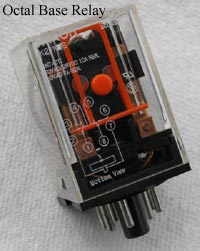
 An octal base relay (like the one shown below) is one of the
most common electrical devices in use today. Also referred to as
general purpose relays, they're widely available in both 8 and
11 pin models, with 8 being the most common. The base of the relay is designed to plug into a
socket, which makes installation and replacement (if required) very easy. An octal base relay (like the one shown below) is one of the
most common electrical devices in use today. Also referred to as
general purpose relays, they're widely available in both 8 and
11 pin models, with 8 being the most common. The base of the relay is designed to plug into a
socket, which makes installation and replacement (if required) very easy.
This basic relay is constructed of 5 main parts:
The Coil
The Armature
The Contacts
The Base (which consists of the socket pins)
The Molded Plastic Frame
The relay works on the principle of electromagnetic force.
When the coil is energized, it becomes magnetized. The armature
(made of a ferromagnetic material and in close proximity to the
coil) - is attracted to the coil by this magnetic force and
moves towards it until it comes to rest against the coil's iron
core.
Attached to the pivoting end of the armature is a spring. The
purpose of the spring is to return the armature to its original
position (away from the coil) when the coil is de-energized.
Also attached to the armature are the arms of the movable set of
contacts (the common contacts). See the illustration below:
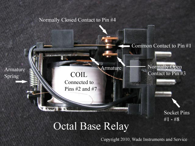
In an 8 pin relay (as shown here) there are 2 common
contacts, 2 normally open contacts, and 2 normally closed
contacts. In an 11 pin relay, there are 3 of each of the
aforementioned. These contacts are made of an electrically
conductive material such as copper. The common contacts have
this material embedded on both sides of the movable arms. The
relationships of all of the contacts is explained as follows:
The common contacts carry the supply voltage that is to be
connected to another electrical device(s). In the de-energized
state of the relay, these common contacts are in contact with
(touching) the normally closed contacts.
Before we go to far, it's important to think of a relay as an
electrical switch. That is, a remote controlled switch, designed
to direct the current path from one part of the circuit to
another. You must also understand that although there are (in
this case) 2 of each type of contact (common, normally open and
normally closed), each is designed to complete a path
independent and separate from the other contact of similar type.
Also, when we use the term "normally closed" it
means that in the normal state of the relay (de-energized) the
common contacts are providing conductive paths to their normally
closed contact partners and only to these contacts. At the same
time, there is no completed paths to the "normally
open" contacts.
So then, when the relay is de-energized, the common contact
#1 is making contact with the normally closed contact #1 and the
common contact #2 is completing a circuit path with the normally
closed contact #2. When the relay is energized, the situation is
reversed. Now the common contact #1 is completing a conductive
path to the normally open contact #1 and at the same time, the
common contact #2 is making contact with the normally open
contact #2. The electrical conductive paths that did exist with
the "normally closed" contacts have now been
"opened". The paths no longer exist.
The Pin Out connections on the base of the relay are as
follows:
Pin #1 = Wired to Common Contact #1
Pin #2 = Wired to One end of the Relay Coil (electricity flowing through
both ends is required to energize)
Pin #3 = Wired to Normally Open Contact #1
Pin #4 = Wired to Normally Closed Contact #1
Pin #5 = Wired to Normally Closed Contact #2
Pin #6 = Wired to Normally Open Contact #2
Pin #7 = Wired to the Other end of the Relay Coil
Pin #8 = Wired to Common Contact #2
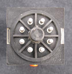
Base of Octal Pin Relay
For other views of the relay, click here.
To further illustrate how a relay works, let's look at it as
it functions within an electrical circuit.
First, we need to know the symbols for the parts of a relay.
The illustration below shows the 3 symbols used in an electrical
schematic to represent the 3 parts: The coil, a normally open
contact and a normally closed contact.
You'll note that there is no symbol representing the common
contact of a relay. That's because it's generally understood that one side
of each of the normally closed and normally open contact symbols
is to be the common contact side. It can be either
side and it depends on how you reference the pin connections in
the drawing. Look at the illustration below as we examine a
pushbutton, relay coil, 2 contacts and 2 lights in a simple control
circuit.
NOTE: ALL
ELECTRICAL SCHEMATIC DIAGRAMS CREATED USING EZ SCHEMATICS
L1 and L2 represents our supply voltage which could be 120
VAC or 24 VDC or something else... it really doesn't matter in
this case. The symbol labeled PB1 represents our push button. It
is shown in the open position. As a footnote, all electrical
schematics are drawn in the de-energized state.
The devices labeled GRN and RED represent our lamps. CR1 is
the relay coil, CR1.1 is one of the normally closed contacts
belonging to the relay CR1 and CR1.2 is one of the normally open
contacts. Note that the pin numbers for the relay parts have
been referenced (refer to the pin out table above for clarity).
RELAY UN-ENERGIZED (as shown above)
When the push button (PB1) is not pressed, current (shown in
purple) is able to flow from L1 through the normally closed
contact CR1.1, through the green lamp (GRN) and back to L2, thus
energizing and illuminating our green lamp.
RELAY ENERGIZED (as shown below)
NOTE: ALL
ELECTRICAL SCHEMATIC DIAGRAMS CREATED USING EZ SCHEMATICS
When the push button (PB1) is pressed, current is able to
flow from L1 through PB1, through the relay coil (CR1) and back
to L2, energizing our relay. At this point, our contacts switch.
All of the contacts that were closed, now open and all of the
contacts that were open, now close.
So, with the relay CR1 energized, the contact CR1.1 opens,
blocking current flow on that path and de-energizing our green
lamp. The contact CR1.2 closes, allowing current to flow from
L1, through the contact CR1.2 and the lamp (RED) and back to L2,
thus energizing and illuminating our red lamp.
Note that the symbols used in the latter drawing (and the
colors as well, for that matter) are for illustrative purposes
only. Remember, electrical schematics are always drawn in the
un-energized state.
These illustrative drawings were created with the software
application EZ Schematics. A
description of the program can be found
here.
Learn
more about relay logic here.
|
